Third part of our series dedicated to the refrigeration circuit of compressed air dryers.
The low pressure circuit
This is the cold part of the refrigeration circuit. Here the gas will give up its negative calories (frigories) to the compressed air to cool it and cause the condensation of water vapor.
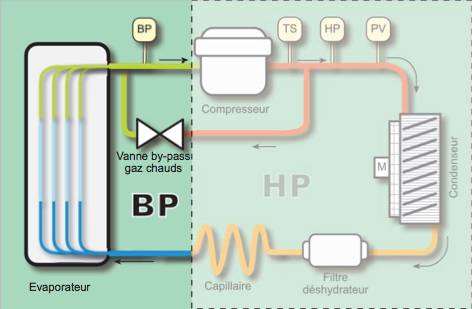
The low pressure begins to come out of the capillary. The strong expansion caused by the latter abruptly lowers the temperature of the liquid. The role of the evaporator (also called air / freon exchanger by the community “aircomprimophile”) is to vaporize the refrigerant during the transfer of calories with the compressed air. It is this heat transfer that will cause the air to cool to the dew temperature. At the outlet of the evaporator, the refrigerant gas is again sucked up by the compressor and the cycle begins again.
In such a system, the cooling capacity is maximum and permanently available. This makes it possible to respond immediately to a sudden increase in the rate of charge of the dryer.
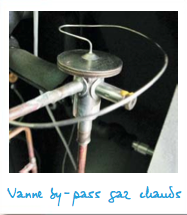
When the requested power is lower, it is necessary to operate in power reduction. This action is entrusted to the hot gas bypass valve. It is a proportional valve which, controlled by both the temperature and the pressure of the gas in the evaporator, will precisely adjust the volume of hot gases to be injected into the latter to maintain the dew point at a constant temperature. , without risk of frost.
The hot gases (coolant brought to high temperature at the compressor outlet) are taken from the H.P. line. The high pressure allows them to be injected into the B.P.
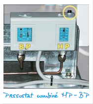
Another safety device is the low pressure switch (BP) on the suction line. Its role is to stop the refrigeration compressor if the pressure drops below a minimum (variable depending on the type of gas used). This pressure switch is automatically reset. This security is generally triggered for 2 main reasons: an empty gas circuit or an obstruction of the HP part. In the latter case, in fact, the gas discharged is blocked in the HP circuit and the compressor then draws the LP part which is then below the critical threshold.
In practice, the low pressure switch is often combined with the high pressure switch. On the photo opposite, we can see the BP part of the pressure switch (with the threshold and differential scales for automatic setting) and the HP part which only has a scale with, in the upper part, the reset (yellow circle).
Simple controls
There are few simple controls on this part of the circuit. By hand, a temperature reading on the suction line of the compressor - dryer running - indicates the production of cold (felt temperature <10 ° C). If the refrigeration unit is stopped and an empty gas circuit is suspected, a shunt on the contact of the pressure switch B.P. will remove any hesitation. (Caution: for testing purposes only, do not allow an empty gas group to run).
As we have seen in these articles, controls use two basic concepts: temperature and pressure. Advanced control of the cold circuit therefore requires a set of refrigeration pressure gauges, which will be the subject of our next issue.